Archive
RPF on the 7750
Burak recently asked for a post on RPF loose and strict modes and how they behave on the 7750. I have quit my job so I have been frantically trying to get things finished and handed over and haven’t had time to really test anything for my own amusement. As I will be finishing up tomorrow and won’t have access to any 7750 lab stuff this is a real quick thrown together post.
We will use a simple network of four routers. All routers have all interfaces in OSPF area 0 with the same cost of 10 on each link. OSPF preference (AD) on the 7750 is 10. We configure a static route on r1-rack3 pointing 1.2.3.4/32 out to r2-rack3, its preference is 5. r1-rack3 is at 10.9.254.28
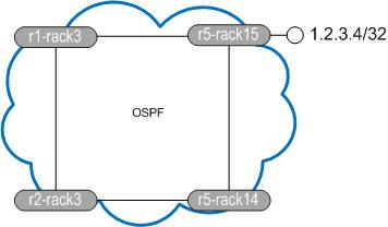
So what does the topology look like from r1-rack3s perspective?
![]()
and what does r5-rack15 think?
![]()
r5-rack15 is going to send traffic on the direct path to r1-rack3 but r1-rack3 thinks 1.2.3.4 should be reachable via r2-rack3. Let’s enable RPF on the interface and see what happens (ignore the IntraAS in the name, it’s from another test).
![]()
I have now enabled loose mode RPF. Theoretically traffic should pass here as once the prefix is in the routing table it should be ok. First clear the statistics (you need to use the urpf-stats variable to clear RPF stats or they won’t clear down)

Now we send a ping from r5-rack15 sourced from 1.2.3.4/32.
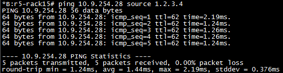
As we can see the pings are successful. This is because even though r1-rack3 uses different egress than the received packets ingress, loose allows more flexibility in what the router will accept.

Happy days, our check fail stats have not increased. Now let’s enable strict mode and see it all fall apart. Strict mode means you MUST receive the packet over the interface you would use to transmit to the destination.
![]()
Now when we ping from r5-rack15 to r1-rack3 we should not see a response to our packets arrive.

In fact debug router ip icmp doesn’t even show up failed attempts. They’re just ignored.
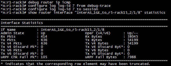
Look at that, beautiful. OK so it’s not a very elegant way of showing how it works but it does. I haven’t found a debug for RPF fails or anything beyond show router interface statistics to display any further RPF information. If you know of any stick it in the comments and I’ll add it.
NG mVPN on the 7750 – let ‘er rip
In the last post in this series we saw how to configure our services on the 7750. This post will show you what actually happens at various stages of service operation. Let’s get started!
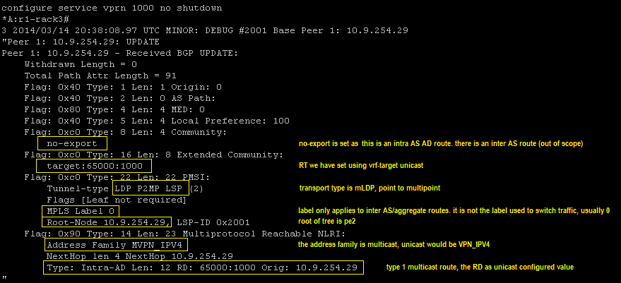
The I-PMSI: Once we no shut the VPRN we will cause the generation of the Intra-AS I-PMSI message to all our BGP peers. r1-rack3 is a route reflector so it will also send that to its clients. As you can see in the embedded text the update carries the RD and originators IP address per the RFC6514 message detail. As we enable the VPRN on each PE the equivalent message will be transmitted and if we create more VPRNs messages will be sent for them with different RDs.
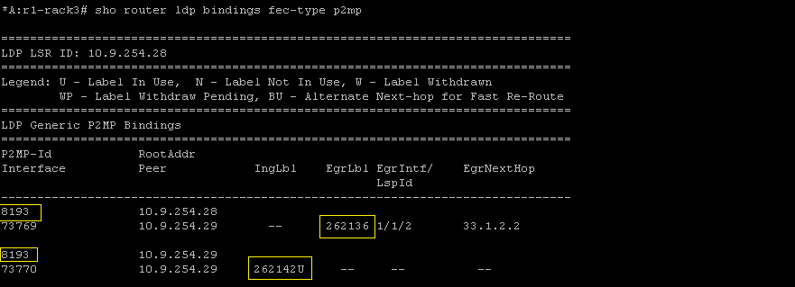
LDP will also allocate labels to the service rooted at each PE.

And finally at this stage let’s look at the LIB. We can see the label we advertised to pe2 is our ingress label with the tunnel ID matching too.
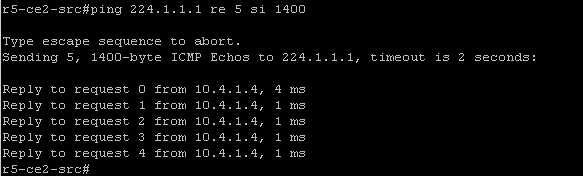
Once every PE knows about all others we have the default tree up and running, the overlay broadcast network. The customer should now be able to traffic. We still have our receiver configured on r4-ce1-rp so now r5-ce2-src is going to transmit to the group and we simulate this by pinging the group address from r5-ce2-src

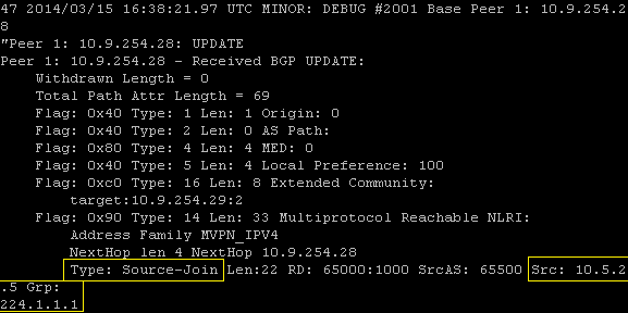
As we are only transmitting 100 bytes we should not trigger the S-PMSI creation at this point. Two things will happen now, each BGP speaker will receive a source join from pe1 connected to r4-ce1-rp (rx) followed by a source active route from pe2 connected to r5-ce2-src (tx).
The source join contains the C-S address (10.5.2.5) and the C-G address (224.1.1.1).
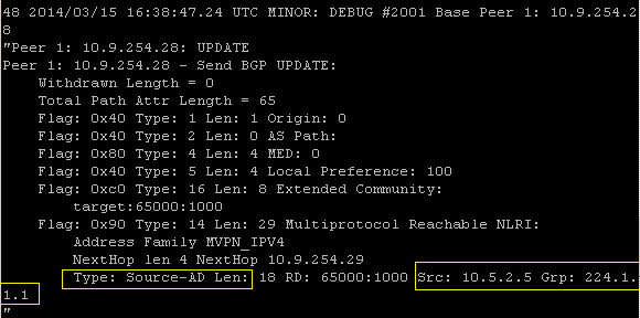
The source active update is sent from the PE connected to the stream source, in our case this is pe2. The mVPN relevant difference between the source join and here is the the ASN is not present in the source active update.
If we take a look at the BGP table we can see the I-PMSI, Source-Active and Source-Join entries.

The S-PMSI: OK so now we have our tree built we can go ahead and ramp up the traffic so that we see the S-PMSI updates. Let’s generate some more ICMP but increase the packet size:
This will cause our data threshold to breach and trigger the sending of S-PMSI from pe2 and traffic to switch over the selective/data tree. Again we see the (C-S, C-G) state highlighted in yellow.

Along with this LDP will allocate and advertise labels for the new tree. Here we send a message to our neighbour advertising label 262129, note the tunnel ID.

The BGP table now has the S-PMSI entry to go along with the other three, let’s have a look.

Once traffic throttles back below the threshold or stops completely the S-PMSI A-D will be withdrawn. As well as the BGP update we can see the LDP withdraw messages exchanged between pe1 and pe2.

So that’s pretty much all I have had time to test on the 7750. If you are interested in the topic I wrote a more vendor agnostic post over on packetpushers.net which I will elaborate on further and have little mini series there too.
Please leave feedback in the comments sections or suggest something else you would like covered.
NG mVPN on the 7750 – make service rocket go now
In the last post we saw a description of how to configure your core to support mLDP based mVPN services and it was admittedly straightforward. The meat of the work happens in the service configuration which we will look at here. I will focus on the configs and save the actual operation of the service for another post as the debug is quite long.
All the mVPN service configuration happens in the, wait for it, mvpn hierarchy. For me one of the most critical parts of the standard is the use of BGP auto-discovery to, well, discover other PE routers in the mVPN without relying on PIM in the core. Let’s configure that first. We have the choice of ‘default’ or ‘mdt-safi’ and we are going to choose ‘default’ as we are not interested in the MDT SAFI. Auto discovery is agnostic to the transport mechanism.
There is a certain order of operations to follow which we will see. Before we can configure C signalling we need to configure the A-D method.

Again more order of operations, before we configure our tunnels we have to enable C multicast signalling. Here we need to choose between BGP and PIM for signalling between the PE routers. As we want to get rid of PIM from our core let’s go with BGP.
![]()
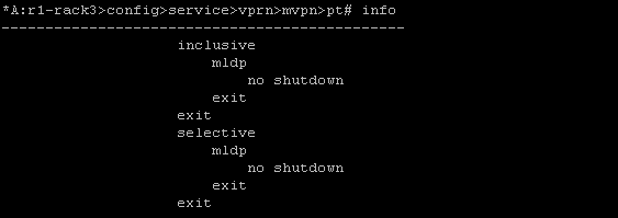
OK now the router is ready for our tunnel configuration. In a Draft Rosen VPN we would need to associate our mdt with a VPN, we don’t have to do that with NG mVPN but we do need to enable transport for our trees. In multicast VPNs we have the concept of the default and data trees which are known as the I-PMSI and S-PMSI respectively. The I-PMSI serves the same function as the default tree, where GRE tunnels are created in Draft Rosen at service initiation. This allows the entire VPN to receive multicast traffic but is not efficient. Why is it inefficient? Any PE without interested receivers connected will still receive traffic on this tree but drop it meaning waste resources in the network. The S-PMSI takes care of this by building a tree between interested PEs only and switching traffic over it, typically when traffic exceeds a particular data rate threshold. To enable these we go in to provider-tunnel and no shut our transport within the I-PMSI or S-PMSI.
We have three options for transport: mLDP, RSVP-TE and PIM
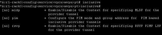
As we are using mLDP for this service we will go ahead and enable that for the inclusive and selective tunnels. We can’t do this if we have not enabled the VRF PIM process, which we took care of in this post
I think this highlights why I am such a fan of SROS. It is so simple to do some pretty complicated things even though you must do things in a specific order. Time was you would have all sorts of crazy patches and elaborate nonsensical configs but this OS I well structured for the most part. Lets not spoil the moment by thinking about QoS and triple play configs :).
If you were in the process of migrating from a PIM core to a pure MPLS one you could enable PIM as your provider tunnel here for nodes that don’t support mLDP. Because this is done on a per service basis you could gradually migrate away from your legacy PIM based core.
Anyway we are just one short commands away from finishing our service and testing it out. If you want you can configure your mVPN specific route targets, maybe you want to import routes at different remote PEs, but if you don’t need to do this you can inherit them from the unicast RT

Thats it! The service should be up because of course we have configured the same thing on each of our participating PEs. So is it up? The tension is killing me…
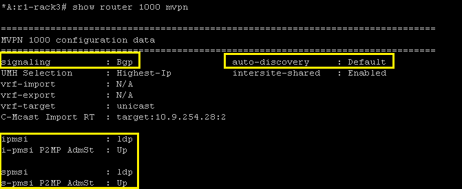
And service is up with mLDP based provider tunnels. The next post will cover what actually happens as we enable service and traffic starts to flow
NG mVPN implementation on the 7750 – Setting up for service
Ok so it has been a while. I have done some testing on LDP based mVPN at this stage, not a huge amount, mainly basic functionality.
The first thing to note is 7750 MUST run in chassis mode D to allow the multicast commands required for mLDP. This means no IOM1 or IOM2 cards are allowed in the chassis and because of this I have a limited topology to play with.

Both PE routers are SR12s running CPM2-400G and have IMMs or IOM3 in the CE facing slots. The CE routers are Cisco 1841, r4-ce1-rp is the RP and also the receiver, it’s config is below. r5-ce2-src simply runs PIM on its uplink to pe2 and will source traffic to group 224.1.1.1.

Roll on up the 7750s. The first task we do is create the VPRN service and place the CE facing interface in to the VRFs PIM process. I have configured the CE facing interface name as “mvpn” just for clarity, it has no bearing on the mVPN configuration. The remainder of the config is exactly the same as standard VPRN. PIM configuration is very straightforward, all I do is enter the PIM process and add the interface. The rest of the config below is defaulted. I won’t be setting the RP address as I think that’s intrusive on the customers experience, they should have the freedom to change their RP as they see fit.

Once we do this, and assuming connectivity is good, we should see a PIM adjacency going up:
![]()
So that is the very basic element complete. Now we just need to do the entire core! Well not so much. Per the diagram above I already have MP-BGP configured and both routers have address family mvpn-ipv4 activated. I also have VPNv4 activated, not much point having mVPN and no IPv4 VPN to use. Would anyone buy that service?

There is one other ‘core’ element we need to verify before we get in to the VRF specific multicast configuration. We need to ensure our network interface will support multicast and the creation of mLDP trees. We simply enable it under the LDP interface…

and if we want to prevent multicast over an interface…
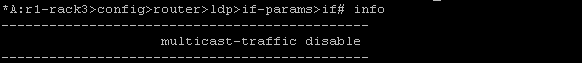
I have links to routers that do not run in mode D so multicast processing should be disabled.
OK so with MP-BGP and LDP multicast enabled we can configure the VPRN to carry the customers traffic. That will come in the next post which will see the VPRN config and debug behaviour when the services comes up and how BGP updates trigger switchover to the S-PMSI.
Multicast of the 7750 – IGMP static joins
Here we will configure IGMP and associate an interface with it. We will also create a static join which is useful for troubleshooting but I guess on a platform like the 7750 you would use it for broadcast TV.
Let’s create an interface first, I’ll call it igmp but the name is irrelevant to the IGMP process.
config router interface igmp

address 3.3.3.3/24

port 1/1/2:3
Now lets start IGMP and associate the interface with the process
config router igmp interface "igmp"
Unshut the process if not already done
So now the interface is there we need to associate the static mapping to it. We wil use group 239.3.3.3. Once we do this we will see a warning message
*A:R3>config>router>igmp>if# static group 239.3.3.3

WARNING: CLI The static group is not yet created because source or starg is not yet specified.
What this means is we need to either set the static source or configure it as ASM, the starg keyword meaning (*,g)
so all we need to do is lash in the keyword and we should see the shared tree back to the RP
starg
And we do, the link to R3 is in the OIL
*A:R4# show router pim group 239.3.3.3 detail

.

===============================================================================

PIM Source Group ipv4

===============================================================================

Group Address      : 239.3.3.3

Source Address     : *

RP Address         : 44.44.44.44

Advt Router        : 44.44.44.44

Flags              :                    Type               : (*,G)

MRIB Next Hop      :

MRIB Src Flags     : self               Keepalive Timer    : Not Running

Up Time            : 0d 00:09:51        Resolved By        : rtable-u

.

Up JP State        : Joined             Up JP Expiry       : 0d 00:00:08

Up JP Rpt          : Not Joined StarG   Up JP Rpt Override : 0d 00:00:00

.

Rpf Neighbor       :

Incoming Intf      :

Outgoing Intf List : R3_1/1/2

.

Curr Fwding Rate   : 0.0 kbps

Forwarded Packets  : 0                  Discarded Packets  : 0

Forwarded Octets   : 0                  RPF Mismatches     : 0

Spt threshold      : 0 kbps             ECMP opt threshold : 7

Admin bandwidth    : 1 kbps

-------------------------------------------------------------------------------

Groups : 1
Short and sweet
