NG mVPN on the 7750 – let ‘er rip
In the last post in this series we saw how to configure our services on the 7750. This post will show you what actually happens at various stages of service operation. Let’s get started!
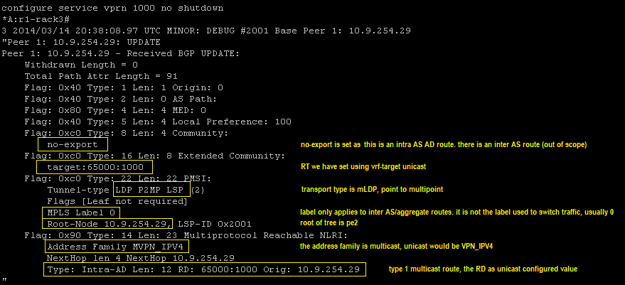
The I-PMSI: Once we no shut the VPRN we will cause the generation of the Intra-AS I-PMSI message to all our BGP peers. r1-rack3 is a route reflector so it will also send that to its clients. As you can see in the embedded text the update carries the RD and originators IP address per the RFC6514 message detail. As we enable the VPRN on each PE the equivalent message will be transmitted and if we create more VPRNs messages will be sent for them with different RDs.
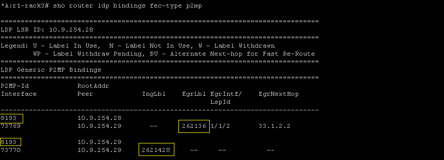
LDP will also allocate labels to the service rooted at each PE.

And finally at this stage let’s look at the LIB. We can see the label we advertised to pe2 is our ingress label with the tunnel ID matching too.
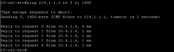
Once every PE knows about all others we have the default tree up and running, the overlay broadcast network. The customer should now be able to traffic. We still have our receiver configured on r4-ce1-rp so now r5-ce2-src is going to transmit to the group and we simulate this by pinging the group address from r5-ce2-src

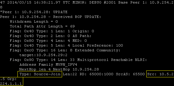
As we are only transmitting 100 bytes we should not trigger the S-PMSI creation at this point. Two things will happen now, each BGP speaker will receive a source join from pe1 connected to r4-ce1-rp (rx) followed by a source active route from pe2 connected to r5-ce2-src (tx).
The source join contains the C-S address (10.5.2.5) and the C-G address (224.1.1.1).
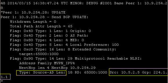
The source active update is sent from the PE connected to the stream source, in our case this is pe2. The mVPN relevant difference between the source join and here is the the ASN is not present in the source active update.
If we take a look at the BGP table we can see the I-PMSI, Source-Active and Source-Join entries.

The S-PMSI: OK so now we have our tree built we can go ahead and ramp up the traffic so that we see the S-PMSI updates. Let’s generate some more ICMP but increase the packet size:
This will cause our data threshold to breach and trigger the sending of S-PMSI from pe2 and traffic to switch over the selective/data tree. Again we see the (C-S, C-G) state highlighted in yellow.

Along with this LDP will allocate and advertise labels for the new tree. Here we send a message to our neighbour advertising label 262129, note the tunnel ID.

The BGP table now has the S-PMSI entry to go along with the other three, let’s have a look.

Once traffic throttles back below the threshold or stops completely the S-PMSI A-D will be withdrawn. As well as the BGP update we can see the LDP withdraw messages exchanged between pe1 and pe2.

So that’s pretty much all I have had time to test on the 7750. If you are interested in the topic I wrote a more vendor agnostic post over on packetpushers.net which I will elaborate on further and have little mini series there too.
Please leave feedback in the comments sections or suggest something else you would like covered.
