Archive
Static RPKI in Nokia SROS15
Here is a quick look at static RPKI on the Nokia 7×50.
Resource Public Key Infrastructure is a security measure which attempts to solve, or minimise, the impact of prefixes being disseminated from invalid source ASNs. This is where an AS will hijack and originate a prefix when it does not own it. Sure this can be because of a legitimate mistake but it can also be used for being naughty.
You can use dynamic or static mappings to confirm the legitimacy of the prefix origination. Here I will use static only.
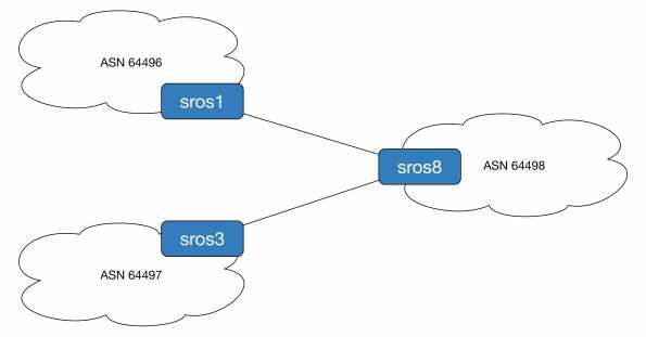
To demonstrate this we will originate prefix 192.0.2.1/32 from ASN 64497 (legitimate owner) and ASN 64496 (naughty people). ASN 64498 will use static mappings to decide which is the source of truth. For reference sros1 is running release 14, sros3 is release 13 and sros8 is the all new release 15 router.
First we configure the loopback addresses and BGP sessions.
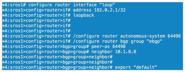
All we have done here is configure a loopback on sros1 of 192.0.2.1/32, set our ASN to 64496 and configured our BGP parameters for our session to sros8. We configure the equivalent BGP config on sros8

We then confirm sros8 is receiving and installing 192.0.2.1/32 as the best path.

Before we look at competing ASNs let’s enable prefix validation on sros8.
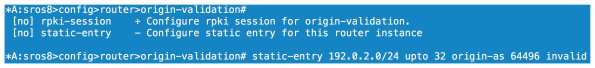
We can configure our dynamic relationship with a server under the rpki-session config context or we can configure statically. As I don’t have the option of using RPKI server mappings right now I choose static. Here we configure an entry that covers anything within 192.0.2.0/24 up to a prefix length of /32. This covers off the 192.0.2.1/32 prefix I am receiving from sros1. We then specify the ASN of the source and either tag it as valid or invalid. Here we are going invalid as we know AS64496 should not be originating this particular prefix.
If we look at our local database on sros8 we can see a flag of Static-I set. This means it is statically configured as invalid.

Now will BGP reject the prefix? 
No because we haven’t told the BGP process to do anything with the origin validation information yet. We need to enable origin validation within the BGP group context.

So now we have enabled origin validation with the BGP group config we still have one step to carry out. As shown above we need to tell the BGP process that anything marked as origin-invalid should be considered unusable. Once we make that change the path will no longer be considered in the best path selection process.
Now what if AS64497 starts legitimately advertising 192.0.2.1/32, will we allow this? One would hope so!

We now have our peering up to both sros1 and sros3, both of which are sending us 192.0.2.1/32.
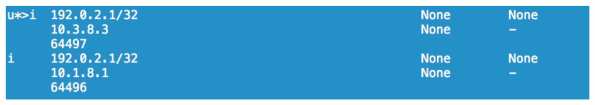
On the prefix received from sros3 we have an origin validation state of NotFound, basically not explicitly valid or invalid. sros1 reports the state as invalid and, as we saw, it cannot be considered for best path determination.

Loophole the BOF
If you have a lab and you want to connect to your SROS routers mgmt interface from wherever, you may know you cannot configure a 0/0 static route. Want to get around it? Configure something like the below.
#### Don’t do this in production! Don’t do it if your lab is not secured ####
*A:r5>bof# static-route 0.0.0.0/0 next-hop 192.0.2.254
MINOR: SYSTEM #1505 Invalid static route destination prefix – cannot configure default route on the management interface
*A:r5>bof# static-route 0.0.0.0/1 next-hop 192.0.2.254
*A:r5>bof# static-route 128.0.0.0/1 next-hop 192.0.2.254
Configuring LDP in SROS
OK so we have configured our IGP and we have full reachability within the core network. In order to provide MPLS VPN services we are going to need some protocol that will signal labels for both the transport addresses and the services. For the transport we can use LDP or RSVP and for services we can use BGP as well. This post will focus on LDP only.
Label Distribution Protocol is pretty much the awesomest protocol you can have. It’s very easy to configure, easy enough to troubleshoot and is scalable. I love it cos it’s difficult to mess up which means less of a mess for me to clean up when someone does!
LDP is the standardized version of Ciscos Tag Distribution Protocol, a.k.a TDP. It was developed by the IETF and is covered in a multitude of RFCs but the basics can be found in RFC5036, LDP Specification. For neighbour discovery (link local), LDP uses UDP port 646 and multicasts to 224.0.0.2. Once discovered, neighbours are maintained through TCP port 646. Targeted peers use the same function except the destination address is explicitly specified and unicast. Have a read of the RFC, it’s not the worst.
Anyway on to the 7750s and how we enable LDP.
Like the majority of protocol happenings the LDP configuration section is within the config router context. Entering the LDP subconfig admin enables the protocol on the router.
A:r2# configure router ldp
Once we have enabled LDP we need to put specific entities in to say where we want LDP to run, what variables we want to attach to each interface and if we want to specify targeted parameters.
First we will put our interfaces in to the process, the interface to r5 is used here:
*A:r2>config>router>ldp# interface-parameters

*A:r2>config>router>ldp>if-params# interface "tor5"

*A:r2>config>router>ldp>if-params>if# exit
Next we will want to specify some peers so that we can do authentication and neighbour specific parameters.
*A:r2>config>router>ldp# peer-parameters

*A:r2>config>router>ldp>peer-params# peer 1.1.1.1

*A:r2>config>router>ldp>peer-params>peer$ authentication-key labldp
Now by far the most useful command with LDP is show router ldp session, it will tell you who you have an adjacency with and if its link local or link local and targeted, displayed as both, and you will want both for services.
Now if we look at our peers we will see nothing to 1.1.1.1 even though we just configured it, wtf!? That’s because you need a reason to signal a targeted session as 1.1.1.1 is not directly connected to r2. You can do this in a couple of ways either by creating an explicit targeted relationship or creating a SDP. We will use targeted here as SDPs will be covered when I get on to services.
*A:r2>config>router>ldp# targeted-session peer 1.1.1.1
Of course we configure the equivalent on the remote side at r1. What is the result? r1 becomes a targeted peer:
*A:r2# show router ldp session
==============================================================================

LDP Sessions

==============================================================================

Peer LDP Id Adj Type State Msg Sent Msg Recv Up Time

------------------------------------------------------------------------------

1.1.1.1:0 Targeted Established 36 35 0d 00:02:56

3.3.3.3:0 Both Established 171473 171428 4d 14:31:48

4.4.4.4:0 Both Established 171551 171613 4d 14:34:36

5.5.5.5:0 Both Established 171369 172009 4d 14:27:47

------------------------------------------------------------------------------

No. of Sessions: 4
So what else can you do to tweak LDP? Interestingly you can enable fast reroute on it but since I only just saw it I have never tried it, maybe give that a go when I get on to RSVP FRR:
*A:r2>config>router>ldp# info detail | match fast

no fast-reroute
Under interface config you can change a few things, nothing really fancy. You can alter the local keepalive timers here but I dont set them away from default as I use the IGP and BFD to determine when something has failed. If you want to its hello # or keepalive #.
You can also bind BFD to the LDP interface by simply typing bfd-enable under the interface.
You can change the transport address away from the system address by setting it to use the interface address itself:
*A:r2>config>router>ldp>if-params>if# transport-address interface
There are lots of other things like tunnel in tunnel, or LDP over RSVP, that you configure here but I will leave those more advanced things for another time. I will finish up with import/export policies and controlling label propagation.
First off I am going to put a loopback interface of 44.44.44.44/32 on r4 and advertise it in to OSPF. This will cause a label to be allocated, or will it? No it won’t, not on a SROS box. On a Cisco router it would but the 7750s (and other SROS routers) will only advertise the system addresses by default. We need to use a policy to cause a label binding.
*A:r4# configure router interface loo44

*A:r4>config>router>if$ address 44.44.44.44/32

*A:r4>config>router>if$ loopback

*A:r4>config>router>if$ back

*A:r4>config>router# ospf area 0 interface "loo44"

*A:r4>config>router>ospf>area>if$ passive
OK so we should have the route in OSPF now but no label associated:
*A:r2# show router route-table | match 44.44.44.44

44.44.44.44/32 Remote OSPF 00h03m41s 10
*A:r2# show router ldp bindings prefix 44.44.44.44/32 | match Match

No Matching Entries Found
So now we create the policy to match our prefix and export it in to LDP:
*A:r4>config>router>policy-options# prefix-list 44

*A:r4>config>router>policy-options>prefix-list$ prefix 44.44.44.44/32 exact

*A:r4>config>router>policy-options>prefix-list$ back

*A:r4>config>router>policy-options# policy-statement add_label

*A:r4>config>router>policy-options>policy-statement$ entry 10

*A:r4>config>router>policy-options>policy-statement>entry$ from prefix-list "44"

*A:r4>config>router>policy-options>policy-statement>entry$ action accept

*A:r4>config>router>policy-options>policy-statement>entry>action$ back

*A:r4>config>router>policy-options>policy-statement>entry$ back

*A:r4>config>router>policy-options>policy-statement$ default-action accept

*A:r4>config>router>policy-options>policy-statement>default-action$ back

*A:r4>config>router>policy-options>policy-statement$ back

*A:r4>config>router>policy-options# commit

*A:r4>config>router>policy-options# /configure router ldp export "add_label"

*A:r4>config>router>policy-options#
We should now see a label for our loopback
*A:r2# show router ldp bindings prefix 44.44.44.44/32

===============================================================================

LDP LSR ID: 2.2.2.2

===============================================================================

Legend: U - Label In Use, N - Label Not In Use, W - Label Withdrawn

WP - Label Withdraw Pending, BU - Alternate Next-hop for Fast Re-Route

===============================================================================

LDP Prefix Bindings

===============================================================================

Prefix IngLbl EgrLbl EgrIntf EgrNextHop

Peer

-------------------------------------------------------------------------------

44.44.44.44/32 131041U 131042 -- --

3.3.3.3

44.44.44.44/32 -- 131038 1/1/4:24 24.24.24.4

4.4.4.4

44.44.44.44/32 131041U 131049 -- --

5.5.5.5

-------------------------------------------------------------------------------

No. of Prefix Bindings: 3
Huzzah!
Now lets look at import policies, this is sooo not a real world example but it gets the point across.
In this example I am using r2 again. It is receiving a label for r4’s system address and allocating one for downstream distribution to r5, nothing unusual with that.
*A:r2# show router ldp bindings prefix 4.4.4.4/32
===============================================================================

LDP LSR ID: 2.2.2.2

===============================================================================

Legend: U - Label In Use, N - Label Not In Use, W - Label Withdrawn

WP - Label Withdraw Pending, BU - Alternate Next-hop for Fast Re-Route

===============================================================================

LDP Prefix Bindings

===============================================================================

Prefix IngLbl EgrLbl EgrIntf EgrNextHop

Peer

-------------------------------------------------------------------------------

4.4.4.4/32 131069U 131069 -- --

3.3.3.3

4.4.4.4/32 -- 131069 1/1/4:24 24.24.24.4

4.4.4.4

4.4.4.4/32 131069U 131066 -- --

5.5.5.5

-------------------------------------------------------------------------------

No. of Prefix Bindings: 3
So here we see we have selected the label of 131069 directly from r4 as this is our IGP shortest path to 4.4.4.4. I am going to create a policy that will deny 4.4.4.4 from the peering to r4. You might think that forces us to use the label from r3 or r5 but as they are not on the IGP best path they wont be active label bindings. The policy will use a prefix list to match 4.4.4.4/32 and deny it, breaking any LSP going to or through r4. OK caveat time, I am only showing this so you see the danger of filtering labels and so this can be avoided. Breaking the LSP is going to get you in lots of trouble, don’t do it unless you have a good reason.
The import policy is configured as follows:
*A:r2# show router policy admin

prefix-list "r4"

prefix 4.4.4.4/32 exact

exit

policy-statement "ldp_import"

entry 10

from

prefix-list "r4"

exit

action reject

exit

default-action accept

exit

exit

*A:r2#
Here we go, successfully broken:
*A:r2# configure router ldp peer-parameters peer 4.4.4.4 import-prefixes "ldp_import"

*A:r2# show router ldp bindings prefix 4.4.4.4/32

===============================================================================

LDP LSR ID: 2.2.2.2

===============================================================================

Legend: U - Label In Use, N - Label Not In Use, W - Label Withdrawn

WP - Label Withdraw Pending, BU - Alternate Next-hop for Fast Re-Route

===============================================================================

LDP Prefix Bindings

===============================================================================

Prefix IngLbl EgrLbl EgrIntf EgrNextHop

Peer

-------------------------------------------------------------------------------

4.4.4.4/32 -- 131069 -- --

3.3.3.3

4.4.4.4/32 -- 131069 -- --

4.4.4.4

-------------------------------------------------------------------------------

No. of Prefix Bindings: 2

===============================================================================

*A:r2#

*A:r2# show router ldp bindings active prefix 4.4.4.4/32

===============================================================================

Legend: (S) - Static (M) - Multi-homed Secondary Support

(B) - BGP Next Hop (BU) - Alternate Next-hop for Fast Re-Route

===============================================================================

LDP Prefix Bindings (Active)

===============================================================================

Prefix Op IngLbl EgrLbl EgrIntf/LspId EgrNextHop

-------------------------------------------------------------------------------

No Matching Entries Found
Finally lets cost out the path to r4 and see the labels over another path working. The excitement is almost too much…
*A:r2# configure router ospf area 0 int tor4 met 65534

*A:r2# show router ldp bindings active prefix 4.4.4.4/32

===============================================================================

Legend: (S) - Static (M) - Multi-homed Secondary Support

(B) - BGP Next Hop (BU) - Alternate Next-hop for Fast Re-Route

===============================================================================

LDP Prefix Bindings (Active)

===============================================================================

Prefix Op IngLbl EgrLbl EgrIntf/LspId EgrNextHop

-------------------------------------------------------------------------------

4.4.4.4/32 Push -- 131069 1/1/3:23 23.23.23.3

4.4.4.4/32 Swap 131069 131069 1/1/3:23 23.23.23.3

-------------------------------------------------------------------------------

No. of Prefix Active Bindings: 2

*A:r2#
OK that’s all I got for this one, next up, hmm, mpls/rsvp maybe? Let’s see…
Configuring Basic OSPF in SROS
This post will cover setting up OSPF as your IGP, IS-IS will be covered separately.
First off we need to enable OSPF. Make sure you have your system interface configured before this point or your RID will be based on the base MAC of the chassis and will look like a public IP.
A:r2# show router interface "system" | match /32

2.2.2.2/32 n/a
If you forget or need to change the RID you need to config router ospf shut followed by config router ospf no shut. There is no command like clear ip ospf process in IOS.
So once we confirm this in place we can go ahead and enable OSPF so let’s do that.
The router will use the system address as the RID but we will statically configure one anyway. We will also make the routers an ASBR. This is quite important as simply redistributing prefixes in to OSPF with a policy doesn’t actually send any prefixes to OSPF without the ASBR command in place, the source of many an early days headaches. We will also enable traffic-engineering extensions so we can run MPLS TE, we will need it later.
BTW configuring something for the first time changes the prompt to $ but as I have already enabled OSPF and am just retyping commands the prompt appears as #
 *A:r2# configure router ospf

*A:r2>config>router>ospf# router-id 2.2.2.2

*A:r2>config>router>ospf# traffic-engineering

*A:r2>config>router>ospf# asbr

*A:r2>config>router>ospf#
At this point OSPF will be up which you can verify through show router ospf status. If you failed to set your system interface address you will see your funny RID in here.
*A:r2>config>router>ospf# show router ospf status

OSPF Cfg Router Id : 2.2.2.2

OSPF Oper Router Id : 2.2.2.2

OSPF Version : 2

OSPF Admin Status : Enabled

OSPF Oper Status : Enabled

Graceful Restart : Enabled

GR Helper Mode : Enabled

Preference : 10

External Preference : 150

Backbone Router : True

Area Border Router : False

AS Border Router : True

Opaque LSA Support : True

Traffic Engineering Support : True
Now we want to configure some interfaces in to the process and we will start by creating area 0.0.0.0. This is where you should place your system interface unless you are a stub area router and not an ABR. The system interface is broadcast type by default and passive so I will set the interface type to point to point, and passive just to demonstrate the command.
*A:r2>config>router>ospf# area 0

*A:r2>config>router>ospf>area# interface "system"

*A:r2>config>router>ospf>area>if# interface-type point-to-point

*A:r2>config>router>ospf>area>if# passive

*A:r2>config>router>ospf>area>if#
Now lets configure an interface in to area 0 and give it some meaningful configuration such as link cost/metric, bind it to the interface BFD instance and force authentication using the password mypassword
*A:r2>config>router>ospf>area# interface "tor3"

*A:r2>config>router>ospf>area>if# interface-type point-to-point

*A:r2>config>router>ospf>area>if# metric 1001

*A:r2>config>router>ospf>area>if# bfd-enable

*A:r2>config>router>ospf>area>if# message-digest-key 1 md5 mypassword

*A:r2>config>router>ospf>area>if# authentication-type message-digest
Next we will configure a stub area, called area 5. In here we will put a link to r5
*A:r2>config>router>ospf# area 5

*A:r2>config>router>ospf>area# stub

*A:r2>config>router>ospf>area>stub# exit

*A:r2>config>router>ospf>area# interface "tor5"

*A:r2>config>router>ospf>area>if# interface-type point-to-point

*A:r2>config>router>ospf>area>if# metric 10101

*A:r2>config>router>ospf>area>if# bfd-enable

*A:r2>config>router>ospf>area>if# message-digest-key 1 md5 mypassword

*A:r2>config>router>ospf>area>if# authentication-type message-digest
To create a Totally Stub Area then we put the no summaries option under the stub configuration.
MTU obviously plays an important part in OSPF and every network engineer has been mind boggled by it at some stage in their career, exchange start anyone? To set it under an interface its simply mtu # where # is the value you apply. The maximum you can set is 9198, on my routers anyway.
A couple of miscellaneous commands now. If you wish to stop advertising subnet routes for an interface you configure no advertise-subnet if that floats your boat. Finally on the basics, if you have DR set up with type 2 LSAs for some reason (not a fan, it’s just messy), you can set the interface priority to bias the DR election. Simply configure the priority # command
Some useful show commands:
We have show router ospf status which we saw earlier
*A:r2# show router ospf neighbor

===============================================================================

OSPF Neighbors

===============================================================================

Interface-Name Rtr Id State Pri RetxQ TTL

Area-Id

-------------------------------------------------------------------------------

tor5 5.5.5.5 Full 1 0 35

0.0.0.0

tor4 4.4.4.4 Full 1 0 33

0.0.0.0

tor3_b 3.3.3.3 Full 1 0 34

0.0.0.0

-------------------------------------------------------------------------------

No. of Neighbors: 3
(Yep I didn’t actually configure area 5 for tor5 🙂 I’m running some tests at the moment so can’t be messin with that!)
show router ospf interface shows you which interfaces you have OSPF running on, the DR/BDR, area and interface type. Unlike show ip ospf interface brief in IOS it doesn’t give you the interface cost. For that you need to use the detail option, which can be for all interfaces or a single one if you specify it:
*A:r2# show router ospf interface "tor4" detail | match "Oper Metric"

Oper Metric : 100 Bfd Enabled : Yes
show router ospf database -or- show router ospf opaque-database (for the TED) gives you access to the OSPF database, strange huh!? You can use the usual qualifiers to get in to more detail on the LSA contents:
*A:r2# show router ospf database

- database [type {router|network|summary|asbr-summary|external|nssa|all}] [area ] [adv-router ]

[] [detail]
I’m not going to show the output of these commands cos it’s just too much space for a post.
So lets assume I have repeated this on 5 routers in the network. We should now have full reachability.
*A:r2# show router route-table

Route Table (Router: Base)

Dest Prefix[Flags] Type Proto Age Pref

Next Hop[Interface Name] Metric

-------------------------------------------------------------------------------

10.0.0.0/8 Remote OSPF 06d19h45m 150

24.24.24.4 1

1.1.1.1/32 Remote OSPF 01d17h10m 10

24.24.24.4 300

2.2.2.2.2/32 Local Local 31d18h16m 0

system 0

3.3.3.3/32 Remote OSPF 01d17h10m 10

24.24.24.4 200

4.4.4.4/32 Remote OSPF 06d19h45m 10

24.24.24.4 100

5.5.5.5/32 Remote OSPF 01d17h40m 10

25.25.25.5 100

13.13.13.0/24 Remote OSPF 01d17h10m 10

24.24.24.4 300

23.23.23.0/24 Local Local 01d18h11m 0

tor3 0

24.24.24.0/24 Local Local 06d19h45m 0

tor4 0

25.25.25.0/24 Local Local 01d19h55m 0

tor5 0

32.32.32.0/24 Local Local 01d17h51m 0

tor3_b 0

34.34.34.0/24 Remote OSPF 01d17h10m 10

24.24.24.4 200

35.35.35.0/24 Remote OSPF 01d17h10m 10

25.25.25.5 200
And we do…
*A:r2# ping 3.3.3.3

PING 3.3.3.3 56 data bytes

64 bytes from 3.3.3.3: icmp_seq=1 ttl=63 time=5.44ms.

64 bytes from 3.3.3.3: icmp_seq=2 ttl=63 time=3.17ms.

^C

ping aborted by user
---- 3.3.3.3 PING Statistics ----

2 packets transmitted, 2 packets received, 0.00% packet loss

round-trip min = 3.17ms, avg = 4.30ms, max = 5.44ms, stddev = 1.13ms

*A:r2# ping 4.4.4.4

PING 4.4.4.4 56 data bytes

64 bytes from 4.4.4.4: icmp_seq=1 ttl=64 time=8.86ms.

64 bytes from 4.4.4.4: icmp_seq=2 ttl=64 time=3.33ms.

^C

ping aborted by user
---- 4.4.4.4 PING Statistics ----

2 packets transmitted, 2 packets received, 0.00% packet loss

round-trip min = 3.33ms, avg = 6.10ms, max = 8.86ms, stddev = 2.76ms

*A:r2# ping 1.1.1.1

PING 1.1.1.1 56 data bytes

64 bytes from 1.1.1.1: icmp_seq=1 ttl=62 time=42.3ms.

64 bytes from 1.1.1.1: icmp_seq=2 ttl=62 time=3.43ms.

^C

ping aborted by user
---- 1.1.1.1 PING Statistics ----

2 packets transmitted, 2 packets received, 0.00% packet loss

round-trip min = 3.43ms, avg = 22.9ms, max = 42.3ms, stddev = 19.5ms


*A:r2# ping 5.5.5.5

PING 5.5.5.5 56 data bytes

64 bytes from 5.5.5.5: icmp_seq=1 ttl=64 time=4.92ms.

64 bytes from 5.5.5.5: icmp_seq=2 ttl=64 time=3.06ms.

^C

ping aborted by user


---- 5.5.5.5 PING Statistics ----

2 packets transmitted, 2 packets received, 0.00% packet loss

round-trip min = 3.06ms, avg = 3.99ms, max = 4.92ms, stddev = 0.926ms
Next up is enabling LDP which is pretty straightforward. TTFN
Base Topology for Further Posts
I have been really busy trying to get stuff done in work so haven’t has a chance to post anything and any spare time goes on study or family so it’s time to rectify that.
This is the topology I will be using for most of the build I do here. If I need to add in other links or devices I will state that.

Naming and numbering conventions:
-Routers are called rx with r1-4 being SR1 chassis and r5 is a SR7.
-System addresses are x.x.x.x
-Interfaces are ‘torx’, e.g. the link from r5 to r2 is tor2
-Point to point addressing follows xy.xy.xy.x/24 where x is the lower numerical rx and y is the higher numeric rx, e.g. the above mentioned link is 25.25.25.2 on r2
I have some testers dotted around the place and a few Ciscos/Junipers connected for various bits I’m doing. I will point out where they are if I end up including them in a post.
First up, OSPF
SROS Interface Configuration – 7750
In this post I will focus on creating interfaces so it will be a short one because there isn’t much to write home about.
The first thing to know about SROS interfaces is they are named and you bind a physical or logical port to them. The naming of the interface is called in all protocols so you need to make sure you get it right and have a clear convention as deleting the interface will destroy the protocols use of the interface. If you have an OSPF interface and you remove the router interface then OSPF will drop and your network maybe go a little crazy.
So how do we configure them? It’s pretty straightforward and there is no need to create here. Good ol’ ALU consistency.
*A:pe1# configure router interface "to_pe2"
And that’s the interface created. We then need to assign our IP address:
*A:pe1>config>router>if$ address 192.168.123.1/24
You can also run ipv6 over interfaces, which is enabled with the ipv6 command. You need to be in chassis mode C at a minimum and I can’t change that right now…You can do pretty much anything standard, icmp6, DHCP, VRRP.
Then we need to bind this to a physical interface:
*A:pe1>config>router>if$ port 2/1/3:123
Next you might want to run BFD over the interface to use very fast failure detection. The 7750 can be configured to support 10ms transmit intervals but it does require configuration relating to the processor. I have never tried it that low so I dont know what impact it will have on processing.
*A:pe1>config>router>if$ bfd 100 receive 100 multiplier 3
You can assign some CPM protection but I haven’t played with this either so I don’t know how it would benefit you. Something for another time when days allow more than 24 hours in them!
If you want, make the interface a loopback but obviously you need to remove your port binding with the no port command.
If you wish to make it an unnumbered interface you simply configure it with unnumbered and specify an interface name or address you want to take the IP address from.
To configure a secondary interface you simply apply secondary x.x.x.x/y
Finally you can configure VRRP with all the standard bits and bobs that entails. Here is a little snippet that creates the interface as the owner, specifies the partner router as .3, sets the priority to 200 so this interface will be the boss unless there is a problem. You can also tell the interface to reply to pings and traces regardless of it’s state as master or backup which is a pretty cool feature. Finally you can set the delay VRRP takes before establishing for situations where you have a link that may be bouncing.
*A:pe1>config>router>if$ vrrp 1 owner

*A:pe1>config>router>if>vrrp$ backup 192.168.123.3

*A:pe1>config>router>if>vrrp$ priority 200

*A:pe1>config>router>if>vrrp$ ping-reply

*A:pe1>config>router>if>vrrp$ traceroute-reply

*A:pe1>config>router>if>vrrp$ init-delay 10
There are some things you can do with BFD in a VRRP instamce but that will have to wait to my Services posts as it’s more relevant here. Anyway today is day 1 of my CCIE SP study so I have to get down to business there.
SROS System Admin and Security
This post will cover the basics of system configuration along with some security such as adding user names but also more advanced features including control plane filters.
First a few commands to get around the config files:
Context Navigation and Hierarchy:
exit drops you back to your previous level of the hierarchy, exit all brings you back to root and back moves you back up one level of the hierarchy.
To enter config mode you simply type configuration (unambiguous commands are self completing)
Typing info will show you configured commands within your present working context, which itself can be viewed with pwc. Using info detail will show all commands in the pwc including defaults, a very useful one!
As mentioned in my previous post / allows you to parse a command that would otherwise not be available.
tree will show you a tree structure of all available commands within your context
Matching:
The availability of pipe commands is very useful in many OS, SROS being no different. You can pipe any show, info or tree command to include or exclude variables but you can’t concatenate multiple matches in to one string:
info | match address will display any lines with ‘address’ in it
info | match match-not address will display all lines excluding ones with ‘address’ in it
info| match pre-lines 10 address will show you the 10 lines of config prior to a line with address in it,
info | match post-lines 10 address will show you the subsequent 10 lines of config if ‘address’ is matched.
Both the pre and post line match commands are very useful for locating config lines in large files. I frequently see files with over 10,000 lines of config, a downside of the granularity of SROS.
You match a string with spaces by using speech marks:
info | match "address 10" will show you anything with address 10 in the line, such as all network 10 addresses configured.
Who-am-I?
Configuring systems for human identification is crucial in an operational environment for obvious reasons. Here we look at configuring systems name, location information, banners and NTP
A:7750# configure system name "pe1"

*A:pe1# configure system

*A:pe1>config>system# location "In a rack somewhere"

*A:pe1>config>system# contact "NOC @ 1234567890"

*A:pe1>config>system# login-control

*A:pe1>config>system>login-control# motd text "This is my router"

*A:pe1>config>system>login-control# pre-login-message "Unauthorized access prohibited"

*A:pe1>config>system>login-control# back

*A:pe1>config>system# time ntp

*A:pe1>config>system>time>ntp# server 10.11.12.13 version 3 prefer

*A:pe1>config>system>time>ntp# no shutdown

*A:pe1>config>system>time>ntp# back

*A:pe1>config>system>time# zone [timezone]
Access Security:
I’m not a security person by any means but it is always something we need to be conscious of. At a minimum we should be setting local authentication on a device. To set up secure access we can configure a local user:
*A:pe1>config>system# security

*A:pe1>config>system>security# password authentication-order tacplus local exit-on-reject
This is pretty straightforward telling the router to use tacacs+ followed by local auth. Should authentication be rejected exit back to the login prompt.
To configure a local user:
*A:pe1>config>system>security# user "myname"

*A:pe1>config>system>security>user# password "mylocalpwd"

*A:pe1>config>system>security>user# access console

*A:pe1>config>system>security>user# console

*A:pe1>config>system>security>user>console# member "administrative"

*A:pe1>config>system>security>user>console# member "default"
To configure tacacs+ return to the system security context:
*A:pe1>config>system>security# tacplus

*A:pe1>config>system>security>tacplus# accounting

*A:pe1>config>system>security>tacplus# authorization

*A:pe1>config>system>security>tacplus# server 1 address 10.12.13.14 secret "mysecretfor1"

*A:pe1>config>system>security>tacplus# server 2 address 10.12.13.15 secret "mysecretfor2"
You can configure stuff for the SAM5620 manager but I won’t go in to hit as I don’t have a test SAM server.
CPM Filters
CPM filters are what protects your processor and it’s protocols for being compromised, such as OSPF neighbours from a specific subnet. These are not available on the SR1. Extreme care should be take as no-shutting the filters before allowing your own access method can disconnect you from the chassis, and there is no remote way to fix it without out of band. In this section we will configure basic SSH access control and OSPF.
SSH:
*A:pe1>config>sys>security# cpm-filter

*A:pe1>config>sys>security>cpm-filter# ip-filter

*A:pe1>config>sys>sec>cpm-filter>ip-filter# entry 10 create

*A:pe1>cfg>sys>sec>cpm>ip-filter>entry# action accept [drop|queue]

*A:pe1>cfg>sys>sec>cpm>ip-filter>entry# match protocol tcp dst-port 22 65535

*A:pe1>cfg>sys>sec>cpm>ip-filter>entry# match src-ip 10.12.13.0/24
OSPF:
*A:pe1>config>sys>security# cpm-filter

*A:pe1>config>sys>security>cpm-filter# ip-filter

*A:pe1>config>sys>sec>cpm-filter>ip-filter# entry 10 create

*A:pe1>cfg>sys>sec>cpm>ip-filter>entry# action accept [drop|queue]

*A:pe1>cfg>sys>sec>cpm>ip-filter>entry# match protocol ospf-igp src-ip 10.12.13.0/24
You should configure all your protocols to be permitted where required and only no shut the CPM filters when you have permitted your own access, e.g. a SSH filter permitting a source subnet you are on. I will post something on CPM protection when I dabble in it, it’s on my list of ‘to investigate’.
The last thing I want to mention under the configure system banner is the chassis mode. This controls service resources including FIB sizes and can be A, B, C or D. The SR1 supports mode A only which is somewhat limited.
Mode B allows 128k MAC FIB entries and the same ipv4 ARP entries. Mode C must be enabled to allow for IPv6 but chassis mode D is the most scalable. Mode D can support up to 500k MAC and an equivalent amount ARP entries. The chassis mode you run can only be as good as the line cards you have installed. If you have IOMv1 or v2 then you cannot run mode D regardless of the amount of higher spec cards. If you have IOMv3/IMM only then you can run mode D. Upgrading a chassis mode does not impact service traffic but downgrading, say from C to B, requires a reboot. It is enabled using configure system chassis-mode [a|b|c|d]
That’s it for this post, the next ones will relate to actual network build. I will do up a Visio with the topology and start at bringing the physical network up.
SROS System Basics
Service Router OS is the operating system that runs on Alcatel-Lucent 7×50 and 7210 routers and switches. It’s a pretty handy OS and I just love it in the same way Kevin Keegan would love it if we beat them. It is well structured and very flexible and, once you get used to it, it kicks the pants off other vendors I have used, in my opinion.
There is a distinct lack of information that I have found on the Internet for configuring these boxes, especially considering the 7750 is apparently number 1 or 2 in the PE market in Europe. In this post I will cover some basic system configurations to get you going.
I will be using SR1 and SR7 routers for config throughout these posts although there are other models available, e.g. SR12. The SR1 has a single processor and line card with two daughter card slots (MDA) whereas the SR7/12 have dual processors and five and ten line card slots respectively.
In this post I will be using an SR7, its processor slots are named A and B and the line cards are numbered 1-5. The active processor is indicated by either A: or B: at the CLI prompt. Each daughter slot is labelled x/1 or x/2, e.g. slot 2 sub-slot 2 is MDA 2/2.
Each processor (SF/CPM) holds a male DB9 console connector (with DCE/DTE toggle switch), RJ45 Ethernet management port and three compact flash slots. The SROS image is stored in cf3 and cf1/2 can be used to store log files etc.
In order to boot the chassis we need to configure the Boot Options File (bof) to locate the image and config files.
To configure the image and config locations point the bof at the directory/file locations. The A: indicates we are on the processor slot A:
 *A:7750#bof

 *A:7750>bof# primary-image cf3:\TiMOS-9.0.R11

 *A:7750>bof# primary-config cf3:/myconfig.cfg
We then need to set the console speed. SROS defaults to 115200 so let’s change it to 9600 because everybody loves that one:
*A:7750>bof# console-speed 9600
It’s also a good idea to enable persistent indexing between reboots, especially if you use SAM5620 to manage the devices (a reload is required for it to take effect):
*A:7750>bof# persist on
Finally, you may want to use the RJ45 port if you don’t have an async device available. It doesn’t register in the Global Routing Table so any configuration here won’t impact on the operation of the router. Lets set the speed, duplex and an address:
*A:7750>bof# address 1.2.3.4/24 active

*A:7750>bof# speed 10|100

*A:7750>bof# duplex full|half
And that’s pretty much it for the bof, just don’t forget to save your work. If you are in the bof context then it is simply save. If you are in any other context you can use /bof save where the use of / allows the subsequent command to be run from any context. This also applies to config and admin level commands too.
Finally a word on saving in general. If the card identifier has a * against it then configuration has not been saved since the last change. You save the ‘running config’ by parsing admin save, again the / allows the command to be run outside its usual context. If the * doesn’t disappear after either an admin save or bof save then you will have to parse the other save command. From the config context I will save both the running and bof configs, notice the * disappears:
*A:7750# configure

*A:7750>config# /admin save

Writing configuration to cf3:\myconfig.cfg

Saving configuration ... OK

Completed.

*A:7750>config# /bof save

Writing BOF to cf3:/bof.cfg ... OK

Completed.

A:7750>config#
So that’s it for my first post on this ALU craic. I plan to build up a network from here on starting at the physical basics all the way up to advanced service configuration.
Happy Christmas.
