NG mVPN on the 7750 – let ‘er rip
In the last post in this series we saw how to configure our services on the 7750. This post will show you what actually happens at various stages of service operation. Let’s get started!
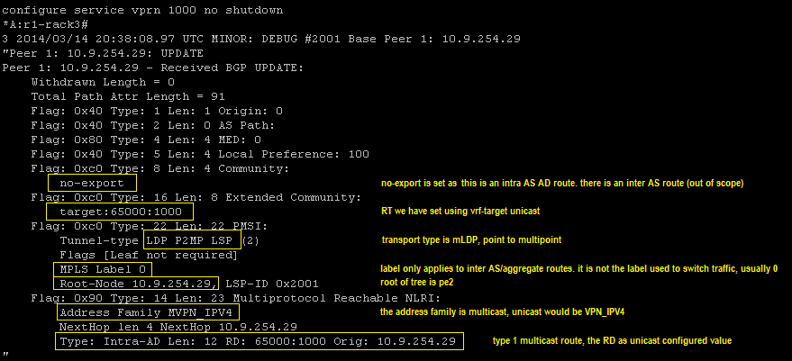
The I-PMSI: Once we no shut the VPRN we will cause the generation of the Intra-AS I-PMSI message to all our BGP peers. r1-rack3 is a route reflector so it will also send that to its clients. As you can see in the embedded text the update carries the RD and originators IP address per the RFC6514 message detail. As we enable the VPRN on each PE the equivalent message will be transmitted and if we create more VPRNs messages will be sent for them with different RDs.
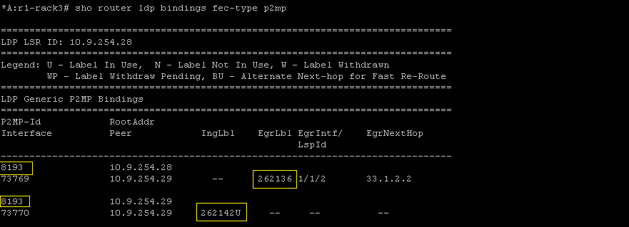
LDP will also allocate labels to the service rooted at each PE.

And finally at this stage let’s look at the LIB. We can see the label we advertised to pe2 is our ingress label with the tunnel ID matching too.
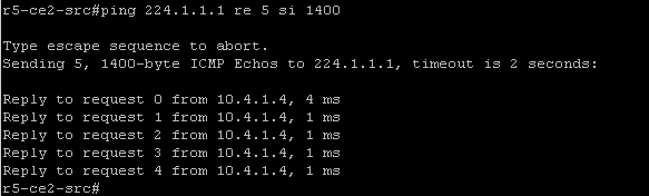
Once every PE knows about all others we have the default tree up and running, the overlay broadcast network. The customer should now be able to traffic. We still have our receiver configured on r4-ce1-rp so now r5-ce2-src is going to transmit to the group and we simulate this by pinging the group address from r5-ce2-src

As we are only transmitting 100 bytes we should not trigger the S-PMSI creation at this point. Two things will happen now, each BGP speaker will receive a source join from pe1 connected to r4-ce1-rp (rx) followed by a source active route from pe2 connected to r5-ce2-src (tx).
The source join contains the C-S address (10.5.2.5) and the C-G address (224.1.1.1).
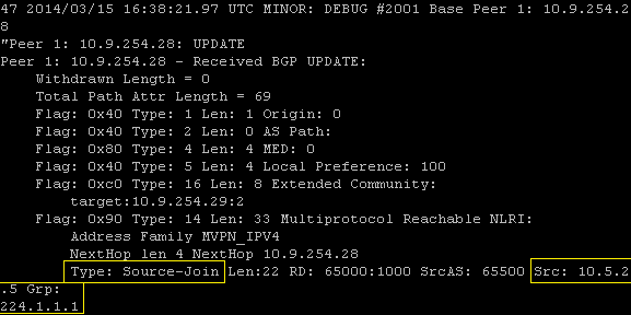
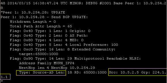
The source active update is sent from the PE connected to the stream source, in our case this is pe2. The mVPN relevant difference between the source join and here is the the ASN is not present in the source active update.
If we take a look at the BGP table we can see the I-PMSI, Source-Active and Source-Join entries.

The S-PMSI: OK so now we have our tree built we can go ahead and ramp up the traffic so that we see the S-PMSI updates. Let’s generate some more ICMP but increase the packet size:
This will cause our data threshold to breach and trigger the sending of S-PMSI from pe2 and traffic to switch over the selective/data tree. Again we see the (C-S, C-G) state highlighted in yellow.

Along with this LDP will allocate and advertise labels for the new tree. Here we send a message to our neighbour advertising label 262129, note the tunnel ID.

The BGP table now has the S-PMSI entry to go along with the other three, let’s have a look.

Once traffic throttles back below the threshold or stops completely the S-PMSI A-D will be withdrawn. As well as the BGP update we can see the LDP withdraw messages exchanged between pe1 and pe2.

So that’s pretty much all I have had time to test on the 7750. If you are interested in the topic I wrote a more vendor agnostic post over on packetpushers.net which I will elaborate on further and have little mini series there too.
Please leave feedback in the comments sections or suggest something else you would like covered.
NG mVPN on the 7750 – make service rocket go now
In the last post we saw a description of how to configure your core to support mLDP based mVPN services and it was admittedly straightforward. The meat of the work happens in the service configuration which we will look at here. I will focus on the configs and save the actual operation of the service for another post as the debug is quite long.
All the mVPN service configuration happens in the, wait for it, mvpn hierarchy. For me one of the most critical parts of the standard is the use of BGP auto-discovery to, well, discover other PE routers in the mVPN without relying on PIM in the core. Let’s configure that first. We have the choice of ‘default’ or ‘mdt-safi’ and we are going to choose ‘default’ as we are not interested in the MDT SAFI. Auto discovery is agnostic to the transport mechanism.
There is a certain order of operations to follow which we will see. Before we can configure C signalling we need to configure the A-D method.

Again more order of operations, before we configure our tunnels we have to enable C multicast signalling. Here we need to choose between BGP and PIM for signalling between the PE routers. As we want to get rid of PIM from our core let’s go with BGP.
![]()
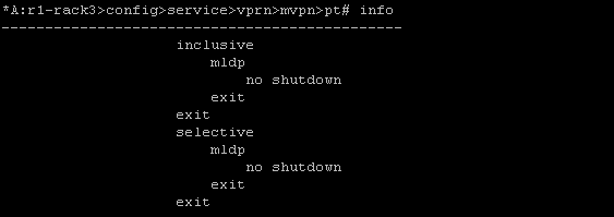
OK now the router is ready for our tunnel configuration. In a Draft Rosen VPN we would need to associate our mdt with a VPN, we don’t have to do that with NG mVPN but we do need to enable transport for our trees. In multicast VPNs we have the concept of the default and data trees which are known as the I-PMSI and S-PMSI respectively. The I-PMSI serves the same function as the default tree, where GRE tunnels are created in Draft Rosen at service initiation. This allows the entire VPN to receive multicast traffic but is not efficient. Why is it inefficient? Any PE without interested receivers connected will still receive traffic on this tree but drop it meaning waste resources in the network. The S-PMSI takes care of this by building a tree between interested PEs only and switching traffic over it, typically when traffic exceeds a particular data rate threshold. To enable these we go in to provider-tunnel and no shut our transport within the I-PMSI or S-PMSI.
We have three options for transport: mLDP, RSVP-TE and PIM
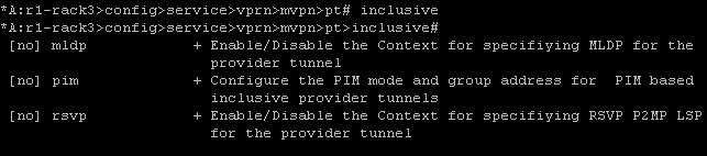
As we are using mLDP for this service we will go ahead and enable that for the inclusive and selective tunnels. We can’t do this if we have not enabled the VRF PIM process, which we took care of in this post
I think this highlights why I am such a fan of SROS. It is so simple to do some pretty complicated things even though you must do things in a specific order. Time was you would have all sorts of crazy patches and elaborate nonsensical configs but this OS I well structured for the most part. Lets not spoil the moment by thinking about QoS and triple play configs :).
If you were in the process of migrating from a PIM core to a pure MPLS one you could enable PIM as your provider tunnel here for nodes that don’t support mLDP. Because this is done on a per service basis you could gradually migrate away from your legacy PIM based core.
Anyway we are just one short commands away from finishing our service and testing it out. If you want you can configure your mVPN specific route targets, maybe you want to import routes at different remote PEs, but if you don’t need to do this you can inherit them from the unicast RT

Thats it! The service should be up because of course we have configured the same thing on each of our participating PEs. So is it up? The tension is killing me…
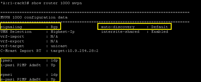
And service is up with mLDP based provider tunnels. The next post will cover what actually happens as we enable service and traffic starts to flow
NG mVPN implementation on the 7750 – Setting up for service
Ok so it has been a while. I have done some testing on LDP based mVPN at this stage, not a huge amount, mainly basic functionality.
The first thing to note is 7750 MUST run in chassis mode D to allow the multicast commands required for mLDP. This means no IOM1 or IOM2 cards are allowed in the chassis and because of this I have a limited topology to play with.

Both PE routers are SR12s running CPM2-400G and have IMMs or IOM3 in the CE facing slots. The CE routers are Cisco 1841, r4-ce1-rp is the RP and also the receiver, it’s config is below. r5-ce2-src simply runs PIM on its uplink to pe2 and will source traffic to group 224.1.1.1.

Roll on up the 7750s. The first task we do is create the VPRN service and place the CE facing interface in to the VRFs PIM process. I have configured the CE facing interface name as “mvpn” just for clarity, it has no bearing on the mVPN configuration. The remainder of the config is exactly the same as standard VPRN. PIM configuration is very straightforward, all I do is enter the PIM process and add the interface. The rest of the config below is defaulted. I won’t be setting the RP address as I think that’s intrusive on the customers experience, they should have the freedom to change their RP as they see fit.

Once we do this, and assuming connectivity is good, we should see a PIM adjacency going up:
![]()
So that is the very basic element complete. Now we just need to do the entire core! Well not so much. Per the diagram above I already have MP-BGP configured and both routers have address family mvpn-ipv4 activated. I also have VPNv4 activated, not much point having mVPN and no IPv4 VPN to use. Would anyone buy that service?

There is one other ‘core’ element we need to verify before we get in to the VRF specific multicast configuration. We need to ensure our network interface will support multicast and the creation of mLDP trees. We simply enable it under the LDP interface…

and if we want to prevent multicast over an interface…
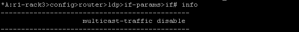
I have links to routers that do not run in mode D so multicast processing should be disabled.
OK so with MP-BGP and LDP multicast enabled we can configure the VPRN to carry the customers traffic. That will come in the next post which will see the VPRN config and debug behaviour when the services comes up and how BGP updates trigger switchover to the S-PMSI.
Multicast of the 7750 – IGMP static joins
Here we will configure IGMP and associate an interface with it. We will also create a static join which is useful for troubleshooting but I guess on a platform like the 7750 you would use it for broadcast TV.
Let’s create an interface first, I’ll call it igmp but the name is irrelevant to the IGMP process.
config router interface igmp

address 3.3.3.3/24

port 1/1/2:3
Now lets start IGMP and associate the interface with the process
config router igmp interface "igmp"
Unshut the process if not already done
So now the interface is there we need to associate the static mapping to it. We wil use group 239.3.3.3. Once we do this we will see a warning message
*A:R3>config>router>igmp>if# static group 239.3.3.3

WARNING: CLI The static group is not yet created because source or starg is not yet specified.
What this means is we need to either set the static source or configure it as ASM, the starg keyword meaning (*,g)
so all we need to do is lash in the keyword and we should see the shared tree back to the RP
starg
And we do, the link to R3 is in the OIL
*A:R4# show router pim group 239.3.3.3 detail

.

===============================================================================

PIM Source Group ipv4

===============================================================================

Group Address      : 239.3.3.3

Source Address     : *

RP Address         : 44.44.44.44

Advt Router        : 44.44.44.44

Flags              :                    Type               : (*,G)

MRIB Next Hop      :

MRIB Src Flags     : self               Keepalive Timer    : Not Running

Up Time            : 0d 00:09:51        Resolved By        : rtable-u

.

Up JP State        : Joined             Up JP Expiry       : 0d 00:00:08

Up JP Rpt          : Not Joined StarG   Up JP Rpt Override : 0d 00:00:00

.

Rpf Neighbor       :

Incoming Intf      :

Outgoing Intf List : R3_1/1/2

.

Curr Fwding Rate   : 0.0 kbps

Forwarded Packets  : 0                  Discarded Packets  : 0

Forwarded Octets   : 0                  RPF Mismatches     : 0

Spt threshold      : 0 kbps             ECMP opt threshold : 7

Admin bandwidth    : 1 kbps

-------------------------------------------------------------------------------

Groups : 1
Short and sweet
Multicast on the 7750 – Quick Intro
I’ve been feeling somewhat lethargic since passing my CCIE. I think it’s actually some sort of trauma, going from 100 in a 50 zone to a dead stop and just lying on the pavement in the rain. I am really struggling with motivation to do anything really outside of work so it’s time to throw off the shackles of post-CCIE depression and get back to doing something interesting. I’m going to be doing some stuff with multicast on the 7750s so this is the first post on it. I haven’t had time to actually do anything of much substance in the lab on it yet so I just knocked up a quick bit of PIM to highlight how easy it is to get basics up and running. It’s not very interesting but it’s a start. I plan to get in to Rosen and mLDP stuff in the future and do a post on inter AS VPN between SROS and XR, maybe Junos if it treats me nice.
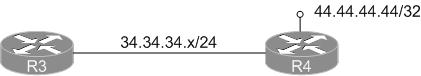
First the topology: R3 and R4 will be PIM neighbours with R4 being our RP.
OK let’s get PIM working:
R4

config router pim

interface system

exit

interface to_R3_1/1/2

exit
R3

config router pim

interface system

exit

interface to_R4_1/1/2

exit
Don’t forget your CPM filters will need to allow PIM through. The above was done on an SR1 which doesn’t support them but they would look something like this:
configure system security cpm-filter ip-filter entry 100

match protocol "pim"

action accept
!!Don’t forget how dangerous misconfiguring filters can be or you will be in the car with your console cable to recover the device!!
Right that should be it for PIM, let’s see if we have neighbour lift off.
*A:R3# show router pim neighbor
===============================================================================

PIM Neighbor ipv4

===============================================================================

Interface Nbr DR Prty Up Time Expiry Time Hold Time

Nbr Address

-------------------------------------------------------------------------------

R4_1/1/2 1 1d 18:47:24 0d 00:01:21 105

34.34.34.4

-------------------------------------------------------------------------------

Neighbors : 1
Great stuff, now we will configure R4 as the RP (bsr and rp candidate) and make sure R3 figures this out. We will use the system address of R4
R4

config router pim

rp

bsr-candidate

address 44.44.44.44

no shutdown

exit

rp-candidate

address 44.44.44.44

no shutdown

exit

exit
And the proof/pudding relationship:
*A:R3# show router pim status | match post-lines 13 BSR

BSR State : Accept Preferred
Elected BSR

Address : 44.44.44.44

Expiry Time : 0d 00:01:19

Priority : 0

Hash Mask Length : 30

Up Time : 1d 18:39:01

RPF Intf towards E-BSR : R4_1/1/2

.

Candidate BSR

Admin State : Down

Oper State : Down

Address : None

Priority : 0

Hash Mask Length : 30

.

Candidate RP

Admin State : Down

Oper State : Down

Address : 0.0.0.0

Priority : 192

Holdtime : 150
So we can see R3 has in fact learned R4 is the BSR. Just to illustrate the point that R3 is not in the running for RP, we can see that both RP and BSR candidate are admin down by default.
Poor mans packet filter
Here is a quick post on how to capture at least some packet header information on a 7750 if you don’t have the luxury of Wireshark to hand. The 7750 allows the creation of mac and IP filters to control traffic in the same way an ACL does on an IOS device. The bonus you have with the Alcatel is that it can also log the header output to a file for review.
Creating a filter is straightforward but care must be taken to ensure you do not disrupt traffic flow when applying it.
First we will configure an IP filter using the default filter log, 101.
*A:r1# configure filter

- filter

[no] ip-filter + Configure an IP-filter

[no] mac-filter + Configure a mac-filter
As you can see we have the option to configure an IP or mac based filter. I have removed other options for now. Creating the filter itself is the first part of the process. Once done the next step is to specify the default action, in our case we want to forward all traffic. This step can be service impacting if not done correctly.
configure filter

ip-filter 99 create

default-action forward
Once that part is done we configure entries for variables we want to match against. To see all traffic we simply set the action to forward here as well. Why do we do this when we have already set the default action? There is no logging option outside of specific entries unfortunately. For the first filter we won’t bother matching anything, we want to capture all traffic.
entry 10 create

action forward

log 101
So that’s the filter done, we just need to apply it to the interface, or SAP, we want to monitor. Here I will apply it to interface tor4 and look at network traffic:
config router inter tor4 ingress filter ip 99
Now we should not have to wait long, as this interface is running OSPF we should see OSPF at least:
show filter log 101

[snip]

2013/11/20 22:19:38 Ip Filter: 99:10 Desc:

Interface: tor4 Direction: Ingress Action: Forward

Src MAC: 14-cf-a4-c0-40-5d Dst MAC: 01-00-5e-00-00-05 EtherType: 0800

Src IP: 41.41.41.4 Dst IP: 224.0.0.5 Flags: 0 TOS: c0 TTL: 1

Protocol: 89

[snip]

2013/11/20 22:19:42 Ip Filter: 99:10 Desc:

Interface: tor4 Direction: Ingress Action: Forward

Src MAC: 14-cf-a4-c0-40-5d Dst MAC: 01-00-5e-00-00-02 EtherType: 0800

Src IP: 41.41.41.4:646 Dst IP: 224.0.0.2:646 Flags: 0 TOS: c0 TTL: 1

Protocol: UDP
So what are we looking at here?
$timestamp Ip Filter: $filternumber:$entry Desc:

Interface:$interfaceID Direction: Ingress Action: Forward

Src MAC: 14-cf-a4-c0-40-5d Dst MAC: 01-00-5e-00-00-05 EtherType: 0800

Src IP: 41.41.41.4 Dst IP: 224.0.0.5 Flags: 0 TOS: c0 TTL: 1

Protocol: 89
Some of this is obvious, some not:
$timestamp: The time at which the packet was logged
$filternumber: the filter ID we configured, in this case 99
$entry: the entry we configured, i.e. 10
$interfaceID: the interface we configured the filter under
Some of the more obvious ones are we set the direction to ingress by putting the filter under ingress at the interface level. Our action on entry 10 was to forward. We are also presented with the source mac/IP which is our neighbour router (remember ingress). The destination is to all OSPF routers so this is a multicast packet. The EtherType indicates the upper layer protocol is IPv4 and the protocol number confirms this is OSPF. While it is useful to see OSPF packets it’s something that is easily seen in a debug.
The second packet in the capture is an LDP packet, an LDP hello in fact as it is UDP directed the all routers multicast address, the port number being used is 646. Maybe LDP isn’t as intuitive to debug, now you can see the traffic live. If we take a look at a mac filter the principle is the same. In this case we will place the filter on a SAP and see customer frames however first we will create a new log file, 102, to show how this is done.
config filter log 102 create

description "SAP_SNIFFER"

destination memory 100

wrap-around

no shutdown
We can send the traps to local memory or we can send them to syslog. With syslog there is more involved and people might not like you trap storming them
Now if we create and apply our mac filter:
mac-filter 99 create

default-action forward

entry 10 create

log 102

action forward

/configure service vpls 1234 sap 1/2/1:1234.0 ingress filter mac 99

show filter log 102

[snip]

2013/11/20 22:52:00 Mac Filter: 99:10 Desc:

SAP: 1/2/1:1234.0 Direction: Ingress Action: Forward

Src MAC: 00-a1-29-5d-b5-75 Dst MAC: 01-b1-c0-40-63 EtherType: 0800

Src IP: 10.9.8.1:1557 Dst IP: 10.9.10.15:162 Flags: 0 TOS: 00 TTL: 255

Protocol: UDP
This message is an SNMP trap being send from a device back to a server as it is using port 162. If we are monitoring SNMP we can leave this filter running for a while and ensure bidirectional communication is happening.
So why would you use a mac filter over an IP filter and vice versa? You can’t apply both to every interface type. In our IP filter example we applied it to a network interface, mac filters are not supported here. You need to choose the right filter for the right occasion.
If you want to look for a specific protocol it’s pretty straightforward. Below we will edit ip filter 99 to match protocol 89. This will then log against OSPF messages:
A:r1>config>filter>ip-filter# entry 10

A:r1>config>filter>ip-filter>entry# match protocol 89

*A:r1>config>filter>ip-filter>entry>match# back

*A:r1>config>filter>ip-filter>entry# info

----------------------------------------------

match protocol ospf-igp

exit

log 101

action forward

----------------------------------------------

*A:r1>config>filter>ip-filter>entry# /clear filter log 101

*A:r1>config>filter>ip-filter>entry# show filter log 101

[snip]

Maximum entries configured : 1000

Number of entries logged   : 1

2013/11/29 09:05:18  Ip Filter: 99:10  Desc:

Interface: tor4  Direction: Ingress  Action: Forward

Src MAC: 14-cf-a4-c0-40-5d  Dst MAC: 01-00-5e-00-00-05  EtherType: 0800

Src IP: 41.41.41.4  Dst IP: 224.0.0.5  Flags: 0  TOS: c0  TTL: 1

Protocol: 89
You can use various different protocol filters, ICMP, TCP or UDP port numbers. Filters can be a useful operational tool for troubleshooting but they can also be dangerous if used incorrectly. Practice using them in a controlled environment and add them to your troubleshooting arsenal.
Using routed VPLS for aggregation and troubleshooting
Everyone surely knows about SVIs, they’re great. They allow you to groom many physical links in to a subnet. If I want to do this on a Cisco that’s all very straightforward, it’s probably one of the first things you learn. Not so easy on a 7750.
Because the 7750 is a service router it isn’t designed to operate as a closet switch. It’s a mean, lean provider router and has a specific purpose. One recent-ish development I came across was the routed VPLS solution. It’s a simple concept, it’s easy to implement but it’s hardware specific. You need to use IOM3 or IMMs to do it which can be sucky, especially if you need its functionality on something like an SR1. This post will look at two scenarios: aggregation and troubleshooting
Aggregation:
OK, I get a request in that a HA pair of voice devices need to be connected in. They must be in the same subnet but they don’t support many features such as VRRP, LACP and I don’t want to do any pre aggregation because that adds extra points of failure, latency which we don’t want for the traffic type. We can’t run any FHRP on the PE so we need to take everything in at layer 2 and have a logical binding to layer 3 in there somehow. My immediate thoughts would be to use an SVI, it’s simple and well understood across operational teams. Unfortunately as we now know this isn’t supported on my 7750. What about using group interfaces? This is where you can aggregate broadband subscribers to a single subnet from multiple MSANs, sounds positive. Unfortunately all testing indicates it’s not going to work, confirmed by the vendor TAC. What can we do then? Didn’t I read something about binding a layer 2 service to a layer 3 interface? Why yes I did. Enter rVPLS.
I need to take 4 connections from a centralized server HA pair and terminate them on a single IP address on the PE. rVPLS allows me to do this by binding a VPLS service to a VPRN. It will look something like this physically.

The first thing you need to do is create the services. If we look at the VPLS first there are only a couple of commands needed outside of a standard configuration, we will put in some make believe SAPs too:
config service vpls 1234

allow-ip-int-binding

service-name "routed vpls"

sap 1/1/1:100

sap 1/1/2:100

sap 2/1/2:100
That’s pretty much it for the VPLS. We need to bind it to our layer 3 interface and we’re done:
config service vprn 4321

interface "gateway" create

address 10.10.10.10/24

vpls "routed vpls"
By specifying vpls "routed vpls" under the interface instead of a SAP or SDP allows hosts on the VPLS to use 10.10.10.10 as their gateway. It’s certainly elaborate compared to an SVI but I do like the concept, giving us more service flexibility.
Troubleshooting:
Here we have a layer 2 broadband aggregation service, the MSAN (CO/FTTx) terminates on an IMM48 and for many reasons we may not have a layer 3 interface to ping from. This is the perfect time to use a routed VPLS if we need to test reachability.
This is a scenario I have used in lab work but never in production. The reason I have not used it in a live environment is you have OAM commands available to carry out diagnostics (cpe ping etc) and therefore probably don’t need it. Of course if you accidentally use an already allocated address it can be impacting to a customer. Use this at your own peril.
So what is the setup? We have a single physical interface to the MSAN from the PE carrying multiple services. Each tagged service comes in to a distinct VPLS on the PE. As this is the last point from the MPLS network to the end user it’s a good place to prove a problem off the core network and in to the access layer.

Our goal here is to configure an ‘interception point’ in to the layer 2 network so we may pin point the fault location further.
If we reuse the configuration from the aggregation example we would simply need to apply the allow-ip-int-binding/service-name commands to the VPLS, create the random VPRN 4321 and set the service name under the VPRN interface, exactly as we did above. Basically this is allowing us to put an intermediate layer 3 pointer in to a layer 2 only service. Once we have completed the configuration steps we can ping the home user. Of course this could be filtered by the end user, the MSAN may have security measures but you get the point, the same logic applies to all media.
A:PE# ping router 4321 10.10.10.143

PING 10.10.10.143 56 data bytes

64 bytes from 10.10.10.143: icmp_seq=1 ttl=64 time=0.150ms.

64 bytes from 10.10.10.143: icmp_seq=2 ttl=64 time=0.125ms.

^C

ping aborted by user

---- 10.10.10.143 PING Statistics ----

2 packets transmitted, 2 packets received, 0.00% packet loss

round-trip min = 0.125ms, avg = 0.137ms, max = 0.150ms, stddev = 0.015ms
So you see we can use this to jump in the middle of PPP sessions to test the connection to the customer or upstream if the BRAS is off the MPLS network domain. Added to that if we have a native ethernet network of 7750s, with no MPLS, then we can use this technique to pin point the problem area in the switched network. I have no idea why you wouldn’t have MPLS if you splashed out on IMMs for your 7750s though! 😀
As a final example before I have some ice cream what if we sell a managed CE service but the core network is using a VPLS. We could use CFM, Y.1731 to measure connectivity. Maybe our end point CE doesn’t support these protocols but it does support IP SLA. We could set an rVPLS interface on each PE and run a local IP SLA echo to measure connectivity in the event of an attachment circuit failure.

I have not tried it before but I think I might. Maybe you know or want to try it for the craic yourself, race ye!
Look what I did – CCIE #40869

I passed the Service Provider CCIE lab exam in Brussels last week. I spent all my free time studying since the new year and finally got my reward. You can read my 3700 something word journey post over here http://ieoc.com/forums/t/27588.aspx. In the mean time I am heading off on holidays for the next couple of weeks for some RnR with my family but when I return I will be back on the ALU tracks.
I have applied to the SRC team to have my CCIE exempt me from taking the BGP exam which I think leaves VPRN, Multicast and Adv Troubleshooting to qualify for the SRA lab exam (I seem to remember a mail from SRC about TPS being removed from the SRA track). I still need to sit the NRS2 lab in the mean time which is where I will be focusing on, until I can get a date and have the cash to take it.
Upcoming posts will focus on the more complicated elements covered in the NRS2 lab.
MPLS tunneling in SROS
I wrote this post ages ago but I have been putting all my time in to CCIE SP labbing and work has been mental so no time for dossing.
Next up I want to look at the basics of MPLS and RSVP configuration. This is an expansive topic and provides a huge amount of flexibility in what you want to achieve with it. This post will cover the basics of setting up interfaces, configuring paths and LSPs.
Let’s get started!
First off we need to know that MPLS and RSVP have a large dependency on each other. Signalling for MPLS tunnels requires RSVP for the path/resv message propagation. We need to configure our interfaces in to the MPLS process and then enable it. Creating an interface in the MPLS context also places it in RSVP, the only thing we need to do is unshut RSVP.
I already have these protocols running so enabling them wont impact anything, it’s simple to configure though
config router mpls no shut
config router rsvp no shut
Below we see how to add an interface in and that it is placed in to RSVP automatically. By simply creating the interface in MPLS we are capable of originating, transiting and terminating LSPs.
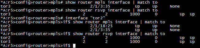
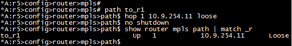
Once we enable this at all interfaces in the network then we are good to go for end to end LSPs. If you don’t enable it on all interfaces then your tunnels may fail to come up, or worse fail in a live environment should there be some convergence. Next let’s create a path from r5 to r1. For now we will create it as a loose path with a single hop to the system address of r1.
Now we need to create the LSP and bind the path to it. We will also enable cspf for future use. This allows the use of constraints to be placed against the LSP such as affinities, SRLG. We need to configure the ‘to’ address as the same as the ultimate endpoint of the path. ‘primary’ gives us the ability to assign the path as the preferred path. You can also assign a ‘secondary’, or multiple secondaries, to the LSP but there isnt much point when using loose paths and no constraints. Maybe just in case you shut down the primary path by mistake.

As we can see from the above screenshot the LSP is now up, only in one direction of course. We have an equivalent path in the opposite direction. Lets have a look at the best troubleshooting command you can use for this, well in my experience.

So above we can see the path the LSP is actually taking in the network goes through r5’s egress interface to r3, r3 ingress from r5 and then terminates at r1. We can also see the labels that have been allocated to the tunnel. If there is an @ beside a hop that means there is a detour available which changes to a # when the detour is in use.
If you want to see the detour path that will be further down the detailed information:
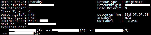
The DetourAvoid will show the interface you must not transit and everything is done automatically, no need to manually build detours yourself.
That’s all I got on this, gotta get back on the Ciscos… Next I will be looking at affinities and how you can control your forwarding path with link colouring, cos that’s kinda cool.
Configuring LDP in SROS
OK so we have configured our IGP and we have full reachability within the core network. In order to provide MPLS VPN services we are going to need some protocol that will signal labels for both the transport addresses and the services. For the transport we can use LDP or RSVP and for services we can use BGP as well. This post will focus on LDP only.
Label Distribution Protocol is pretty much the awesomest protocol you can have. It’s very easy to configure, easy enough to troubleshoot and is scalable. I love it cos it’s difficult to mess up which means less of a mess for me to clean up when someone does!
LDP is the standardized version of Ciscos Tag Distribution Protocol, a.k.a TDP. It was developed by the IETF and is covered in a multitude of RFCs but the basics can be found in RFC5036, LDP Specification. For neighbour discovery (link local), LDP uses UDP port 646 and multicasts to 224.0.0.2. Once discovered, neighbours are maintained through TCP port 646. Targeted peers use the same function except the destination address is explicitly specified and unicast. Have a read of the RFC, it’s not the worst.
Anyway on to the 7750s and how we enable LDP.
Like the majority of protocol happenings the LDP configuration section is within the config router context. Entering the LDP subconfig admin enables the protocol on the router.
A:r2# configure router ldp
Once we have enabled LDP we need to put specific entities in to say where we want LDP to run, what variables we want to attach to each interface and if we want to specify targeted parameters.
First we will put our interfaces in to the process, the interface to r5 is used here:
*A:r2>config>router>ldp# interface-parameters

*A:r2>config>router>ldp>if-params# interface "tor5"

*A:r2>config>router>ldp>if-params>if# exit
Next we will want to specify some peers so that we can do authentication and neighbour specific parameters.
*A:r2>config>router>ldp# peer-parameters

*A:r2>config>router>ldp>peer-params# peer 1.1.1.1

*A:r2>config>router>ldp>peer-params>peer$ authentication-key labldp
Now by far the most useful command with LDP is show router ldp session, it will tell you who you have an adjacency with and if its link local or link local and targeted, displayed as both, and you will want both for services.
Now if we look at our peers we will see nothing to 1.1.1.1 even though we just configured it, wtf!? That’s because you need a reason to signal a targeted session as 1.1.1.1 is not directly connected to r2. You can do this in a couple of ways either by creating an explicit targeted relationship or creating a SDP. We will use targeted here as SDPs will be covered when I get on to services.
*A:r2>config>router>ldp# targeted-session peer 1.1.1.1
Of course we configure the equivalent on the remote side at r1. What is the result? r1 becomes a targeted peer:
*A:r2# show router ldp session
==============================================================================

LDP Sessions

==============================================================================

Peer LDP Id Adj Type State Msg Sent Msg Recv Up Time

------------------------------------------------------------------------------

1.1.1.1:0 Targeted Established 36 35 0d 00:02:56

3.3.3.3:0 Both Established 171473 171428 4d 14:31:48

4.4.4.4:0 Both Established 171551 171613 4d 14:34:36

5.5.5.5:0 Both Established 171369 172009 4d 14:27:47

------------------------------------------------------------------------------

No. of Sessions: 4
So what else can you do to tweak LDP? Interestingly you can enable fast reroute on it but since I only just saw it I have never tried it, maybe give that a go when I get on to RSVP FRR:
*A:r2>config>router>ldp# info detail | match fast

no fast-reroute
Under interface config you can change a few things, nothing really fancy. You can alter the local keepalive timers here but I dont set them away from default as I use the IGP and BFD to determine when something has failed. If you want to its hello # or keepalive #.
You can also bind BFD to the LDP interface by simply typing bfd-enable under the interface.
You can change the transport address away from the system address by setting it to use the interface address itself:
*A:r2>config>router>ldp>if-params>if# transport-address interface
There are lots of other things like tunnel in tunnel, or LDP over RSVP, that you configure here but I will leave those more advanced things for another time. I will finish up with import/export policies and controlling label propagation.
First off I am going to put a loopback interface of 44.44.44.44/32 on r4 and advertise it in to OSPF. This will cause a label to be allocated, or will it? No it won’t, not on a SROS box. On a Cisco router it would but the 7750s (and other SROS routers) will only advertise the system addresses by default. We need to use a policy to cause a label binding.
*A:r4# configure router interface loo44

*A:r4>config>router>if$ address 44.44.44.44/32

*A:r4>config>router>if$ loopback

*A:r4>config>router>if$ back

*A:r4>config>router# ospf area 0 interface "loo44"

*A:r4>config>router>ospf>area>if$ passive
OK so we should have the route in OSPF now but no label associated:
*A:r2# show router route-table | match 44.44.44.44

44.44.44.44/32 Remote OSPF 00h03m41s 10
*A:r2# show router ldp bindings prefix 44.44.44.44/32 | match Match

No Matching Entries Found
So now we create the policy to match our prefix and export it in to LDP:
*A:r4>config>router>policy-options# prefix-list 44

*A:r4>config>router>policy-options>prefix-list$ prefix 44.44.44.44/32 exact

*A:r4>config>router>policy-options>prefix-list$ back

*A:r4>config>router>policy-options# policy-statement add_label

*A:r4>config>router>policy-options>policy-statement$ entry 10

*A:r4>config>router>policy-options>policy-statement>entry$ from prefix-list "44"

*A:r4>config>router>policy-options>policy-statement>entry$ action accept

*A:r4>config>router>policy-options>policy-statement>entry>action$ back

*A:r4>config>router>policy-options>policy-statement>entry$ back

*A:r4>config>router>policy-options>policy-statement$ default-action accept

*A:r4>config>router>policy-options>policy-statement>default-action$ back

*A:r4>config>router>policy-options>policy-statement$ back

*A:r4>config>router>policy-options# commit

*A:r4>config>router>policy-options# /configure router ldp export "add_label"

*A:r4>config>router>policy-options#
We should now see a label for our loopback
*A:r2# show router ldp bindings prefix 44.44.44.44/32

===============================================================================

LDP LSR ID: 2.2.2.2

===============================================================================

Legend: U - Label In Use, N - Label Not In Use, W - Label Withdrawn

WP - Label Withdraw Pending, BU - Alternate Next-hop for Fast Re-Route

===============================================================================

LDP Prefix Bindings

===============================================================================

Prefix IngLbl EgrLbl EgrIntf EgrNextHop

Peer

-------------------------------------------------------------------------------

44.44.44.44/32 131041U 131042 -- --

3.3.3.3

44.44.44.44/32 -- 131038 1/1/4:24 24.24.24.4

4.4.4.4

44.44.44.44/32 131041U 131049 -- --

5.5.5.5

-------------------------------------------------------------------------------

No. of Prefix Bindings: 3
Huzzah!
Now lets look at import policies, this is sooo not a real world example but it gets the point across.
In this example I am using r2 again. It is receiving a label for r4’s system address and allocating one for downstream distribution to r5, nothing unusual with that.
*A:r2# show router ldp bindings prefix 4.4.4.4/32
===============================================================================

LDP LSR ID: 2.2.2.2

===============================================================================

Legend: U - Label In Use, N - Label Not In Use, W - Label Withdrawn

WP - Label Withdraw Pending, BU - Alternate Next-hop for Fast Re-Route

===============================================================================

LDP Prefix Bindings

===============================================================================

Prefix IngLbl EgrLbl EgrIntf EgrNextHop

Peer

-------------------------------------------------------------------------------

4.4.4.4/32 131069U 131069 -- --

3.3.3.3

4.4.4.4/32 -- 131069 1/1/4:24 24.24.24.4

4.4.4.4

4.4.4.4/32 131069U 131066 -- --

5.5.5.5

-------------------------------------------------------------------------------

No. of Prefix Bindings: 3
So here we see we have selected the label of 131069 directly from r4 as this is our IGP shortest path to 4.4.4.4. I am going to create a policy that will deny 4.4.4.4 from the peering to r4. You might think that forces us to use the label from r3 or r5 but as they are not on the IGP best path they wont be active label bindings. The policy will use a prefix list to match 4.4.4.4/32 and deny it, breaking any LSP going to or through r4. OK caveat time, I am only showing this so you see the danger of filtering labels and so this can be avoided. Breaking the LSP is going to get you in lots of trouble, don’t do it unless you have a good reason.
The import policy is configured as follows:
*A:r2# show router policy admin

prefix-list "r4"

prefix 4.4.4.4/32 exact

exit

policy-statement "ldp_import"

entry 10

from

prefix-list "r4"

exit

action reject

exit

default-action accept

exit

exit

*A:r2#
Here we go, successfully broken:
*A:r2# configure router ldp peer-parameters peer 4.4.4.4 import-prefixes "ldp_import"

*A:r2# show router ldp bindings prefix 4.4.4.4/32

===============================================================================

LDP LSR ID: 2.2.2.2

===============================================================================

Legend: U - Label In Use, N - Label Not In Use, W - Label Withdrawn

WP - Label Withdraw Pending, BU - Alternate Next-hop for Fast Re-Route

===============================================================================

LDP Prefix Bindings

===============================================================================

Prefix IngLbl EgrLbl EgrIntf EgrNextHop

Peer

-------------------------------------------------------------------------------

4.4.4.4/32 -- 131069 -- --

3.3.3.3

4.4.4.4/32 -- 131069 -- --

4.4.4.4

-------------------------------------------------------------------------------

No. of Prefix Bindings: 2

===============================================================================

*A:r2#

*A:r2# show router ldp bindings active prefix 4.4.4.4/32

===============================================================================

Legend: (S) - Static (M) - Multi-homed Secondary Support

(B) - BGP Next Hop (BU) - Alternate Next-hop for Fast Re-Route

===============================================================================

LDP Prefix Bindings (Active)

===============================================================================

Prefix Op IngLbl EgrLbl EgrIntf/LspId EgrNextHop

-------------------------------------------------------------------------------

No Matching Entries Found
Finally lets cost out the path to r4 and see the labels over another path working. The excitement is almost too much…
*A:r2# configure router ospf area 0 int tor4 met 65534

*A:r2# show router ldp bindings active prefix 4.4.4.4/32

===============================================================================

Legend: (S) - Static (M) - Multi-homed Secondary Support

(B) - BGP Next Hop (BU) - Alternate Next-hop for Fast Re-Route

===============================================================================

LDP Prefix Bindings (Active)

===============================================================================

Prefix Op IngLbl EgrLbl EgrIntf/LspId EgrNextHop

-------------------------------------------------------------------------------

4.4.4.4/32 Push -- 131069 1/1/3:23 23.23.23.3

4.4.4.4/32 Swap 131069 131069 1/1/3:23 23.23.23.3

-------------------------------------------------------------------------------

No. of Prefix Active Bindings: 2

*A:r2#
OK that’s all I got for this one, next up, hmm, mpls/rsvp maybe? Let’s see…
